


The following paper provides a detailed look at the creation of an innovative, brutally strong manual transmission for high performance street-driven cars and trucks. To my knowledge this is the first time that a manual transmission has surpassed the input torque capacity of the strongest automatics in such applications.
Background
Back in the early seventies it didn’t take long for an impressionable teenage boy to learn that the fastest cars in Augusta, Georgia, had a clutch pedal and a four-on-the-floor. So it was natural that my ‘66 Chevelle Super Sport 396 fit this mold, with its Muncie four-speed transmission and iconic Hurst shifter poking through the floorboard. It soon became clear that Muncies—which came to be derided as “Munchies”—weren’t up to my juvenile antics, as glass-like gears shattered left and right. The local towing service awarded my faithful business with half-price discounts. The last straw was trashing a transmission in grand style, as in cleaning the teeth off second gear and splitting the case wide open.
Lying under the car eating 90-weight gear oil, obvious questions popped up: Wouldn’t it be great to have a truly bulletproof transmission? What were the options? Being a “real” seventies hot rodder, an automatic was out of the question. Some said Ford and Chrysler four speeds were stronger, but only marginally so. Alas, I didn’t see any options—and thus, a seed was planted.
Hot rodding took a back seat to engineering school and a career. That seed must still have been growing, however, because decades later I began to get the itch to create a bulletproof transmission. The aftermarket had been playing catch-up, with Richmond street five speeds rated to handle 450 ft. lbs. Trouble was, a mild big block could easily exceed that.
Experienced manual transmission mechanics will tell you that all passenger car and light truck transmissions have a single countershaft, or a “cluster gear” in hot rod parlance. What about using twin cluster gears to double torque capacity? Big trucks have twin cluster gears, and Mack even has a triple. Liberty’s in Detroit makes a strong twin-cluster transmission for NHRA Pro Stock drag racing. The lack of synchronizers and downshifting capability, as well as the incessant whine of spur gears, caused me to set about designing a more civilized twin-cluster transmission, based on a single-cluster Richmond five speed donor.
It seemed pretty straightforward, to use the input and mainshaft assemblies from the donor transmission and make a new case to house twin cluster gears, with a new extension housing to match. Well, things got tricky fast when going from one cluster gear to two. For those intimately familiar with the workings of single and twin-cluster manual transmissions, what follows is old news. For the uninitiated, a primer is in order.
Manual Transmission Basics
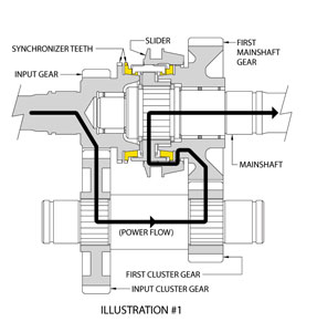
Let’s say you have a simple two-speed manual transmission in first gear (Figure 1). Power flow is from the input gear to the cluster gear. The cluster gear is nothing more than a collection of two or more gears of different tooth counts mounted in series along a common shaft and rotating as a unit. The input gear meshes with the input cluster gear at one end of the cluster shaft. Power is transmitted along the cluster shaft to first cluster gear at the opposite end. The first cluster gear meshes with the first mainshaft gear. Since the transmission is in first gear, a circular array of small synchronizer teeth on first mainshaft gear engage matching teeth on a slider. The slider is splined to a hub, which in turn is splined to the mainshaft, thereby coupling first gear to the mainshaft.
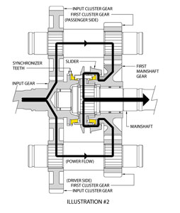
Now, let’s say you have a two-speed twin-cluster transmission in first gear (Figure 2). The layout is identical to the first illustration, only with a second cluster gear added. Power from the input gear is directed to both input cluster gears. Power is transmitted along both cluster shafts to both first cluster gears. Both first cluster gears drive first mainshaft gear. With everything working as it should, the twin-cluster geartrain in Figure 2 will handle twice the torque as the single-cluster geartrain in Figure 1, even though the gears are identically sized.
Carefully consider this paragraph, for the plot suddenly thickens: If both first cluster gears make equal drive contact with first mainshaft gear, each cluster shaft will transmit exactly half of the power. That’s an awfully big “if” since this is only possible if the cluster gears are exactly timed, and the shaft bores are machined in the case so that all shaft axes lie in exactly the same plane. Even a tiny deviation from these perfect conditions will cause either the driver side or passenger side first cluster gear to make initial drive contact with first mainshaft gear. When this happens, it’s possible that only one cluster gear will be transmitting power, and the other will be along for the ride.
Back in the sixties, the Eaton Corporation understood that provisions must be made for imperfect gears and cases. The result, U.S. Patent 3,105,395, describes the world’s first commercially successful twin cluster transmission. The design allows the mainshaft gears to radially float within narrow limits, captured only by the opposing cluster gears. In other words, the rotational axis of each mainshaft gear is allowed to deviate within narrow limits from the common input shaft/mainshaft rotational axis. If a cluster gear were slightly advanced or retarded relative to its neighbor, the mainshaft gear would shift slightly off-center so that the cluster gears equally transmitted power. You’ll see this embodiment in Figure 3. Unlike figures 1 and 2, there is no bearing to support and center first mainshaft gear on the mainshaft. Indeed, the gear is radially supported only by the opposing cluster gears.
The design was a brilliant solution to equalize cluster gear loading, while accommodating normal production gear and case machining variations. However, the resulting gear-to-shaft offset created another problem. Conventional Synchromesh gear synchronizers require close alignment between the engaging members for smooth, quiet, low-effort shifts. This close alignment was lost by the very nature of Eaton’s design. So, Synchromesh gear engagement was out of the question. Instead, relatively crude jaw-tooth gear engagement was substituted, with wide engagement “windows,” which easily accommodated the radial misalignment (see Figure 3). The trade-off? Double-clutching, gear-grinding, clunky shifts.
In the years since, many big truck transmissions have benefited from the addition of sophisticated electronics and shifting mechanisms. Gear engagement windows are now electronically anticipated, so that smoother computer-assisted shifting is commonplace. Although modern twin-cluster big truck transmissions are smoother-shifting, I wanted to create my own scaled-down, strong, smooth-shifting twin-cluster manual transmission void of complex, expensive, computer-assisted shift mechanisms. In short, marrying ordinary Synchromesh gear synchronization with twin cluster gears.
Another Inspiration
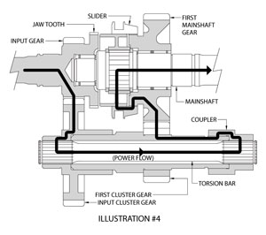
Years of reading car magazines revealed a seemingly unrelated innovation by Doug Nash Equipment and Engineering. Back in the seventies Nash was developing a true clutchless drag racing transmission. Early experiments were conducted in famed racer Don Nicholson’s car. The instantaneous shifts imparted huge shock loads, regularly breaking transmissions, drive shafts, and rear axles. I felt an instant kinship. Eventually, Doug fitted a torsion bar inside a tubular cluster shaft (Figure 4 shows a simplified two-speed version). Power transfers from the input gear to the input cluster gear. However, unlike previous illustrations, the input cluster gear is not directly coupled to the cluster shaft—in fact, the input cluster gear is a clearance fit on the cluster shaft, allowing independent rotation. Instead, the input cluster gear is splined to one end of the torsion bar. The torsion bar exits the other end of the cluster shaft, where a splined coupler connects the torsion bar to the cluster shaft. So the input cluster gear is coupled to the remainder of the cluster gear assembly only by the torsion bar. During high rpm launches and clutchless gear changes the high-strength torsion bar momentarily twists, substantially reducing shock loads. Doug said the torsion bar flat solved the driveline breakage problems for years to follow. As a bonus, quarter mile elapsed times slightly improved, because the drive wheels maintained better traction during “softer” launches and gear changes—yet another brilliant solution to a vexing engineering problem.
A New Design Twist
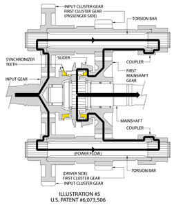
With this background information, a way of accommodating synchronizers and twin cluster gears in one transmission design became evident, using only four main design features (Figure 5 shows a simplified two-speed version):
1) Bearing-supported mainshaft gears (as in an ordinary single-cluster transmission). This ensures synchronizer alignment during gear shifts, for smooth, quiet, low-effort shifts.
2) Use torsion bars inside both tubular cluster shafts. Now, for example, if the transmission is in first gear, and the driver side first cluster gear is slightly advanced relative to the passenger side first cluster gear, the driver first cluster gear will make initial drive contact with first mainshaft gear. At that instant the driver torsion bar will begin twisting a small amount, allowing the passenger first cluster gear to advance until it also makes drive contact with first mainshaft gear. The torsion bars are sized so that the accommodated timing error is a very small percentage of the total available twist. Consequently, cluster gear loading is very nearly equalized.
3) Since the mainshaft gears are not allowed to radially float, consider that tooth mesh interference would prevent transmission assembly if cluster gear timing error (up to +/- 0.3 degree in the prototype) exceeded available gear tooth backlash. To counter this, +/- 0.6 degree of spline backlash is introduced between the cluster shaft and each cluster gear, so that timing errors are accommodated without tooth mesh interference. Figure 6
4) To reduce manufacturing costs, the input cluster gears and the torsion bars are made without timing specifications. Instead, a vernier adjustment allows for indexing the input cluster gears to the remainder of the cluster assemblies. As the cluster assemblies are placed in the case, timing marks on the cluster gears align with corresponding marks on the mainshaft gears. The input cluster gears randomly engage the input gear. After the cluster gears are installed, one splined coupler is installed on the torsion bar splines. Then the coupler is rotated slightly to engage the cluster shaft splines. Now, to index the second coupler it’s useful to know that the torsion bars have 31 splines and the cluster shaft has 32. This creates a vernier adjustment between the remaining torsion bar and cluster shaft, having 0.36 degree adjustment increments. The second coupler is installed on the torsion bar splines, then an attempt is made to engage the cluster shaft splines. If the coupler won’t engage both sets of splines, the coupler is removed, rotated one spline, and reinstalled on the torsion bar. A second attempt is made to engage the cluster shaft splines. This sequence is repeated until the second coupler engages both sets of splines. The input cluster gears are now indexed to the remainder of the cluster gear assemblies.
Radical Results
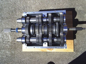
What’s the upshot of all this? Owing to the twin cluster gears, the geartrain in the Richmond five speed-based prototype (pictured) can handle 900 ft. lbs of input torque, up from 450. Certainly strong enough to handle anything I put in front of it. However, the design is not limited to Richmond-based transmissions. It’s adaptable to a wide range of single-cluster transmission designs. If adapted to Tremec’s T56 Magnum six speed, for example, torque capacity would increase from 700 ft. lbs. to 1,400. That’s a far cry from the estimated 350 ft. lbs. rating of my old wide-ratio “Munchie.” What’s more, by incorporating Synchromesh gear synchronization into the design, the box shifts smoothly and quietly. Figure 7
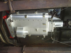
As long as automatics have been around, with their inherently strong planetary gearing, they’ve enjoyed a strength advantage over manuals—until now. Perhaps the strongest automatic of all time for car and light truck use is GM’s 4L85E, rated at 850 ft. lbs. input torque. With the prototype’s 900 ft. lbs. rating, and the promise of even higher numbers to come, that “automatic advantage” has officially evaporated. Figure 8


