


The contact on single enveloping worm gear drives is the line contact. The changing form of the worm across the face of the gear makes it impossible to derive a simple mathematical expression for the contact curvature. In addition, the combination of the lead angle of the worm and position of the pitch plane of the worm in reference to the worm thread profile has predominant influence on the position and form of the actual contact line. The author here presents a report on the relative curvature of the worm and wheel at sections parallel to the axial section of a worm.
Curvature & Radius of Curvature
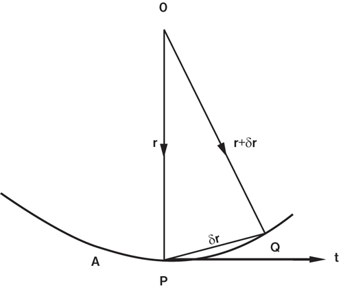
A curve is the locus of a point whose position vector r relative to a fixed origin may be expressed as a function of a single variable parameter. It is usually convenient to choose as the scalar parameter the length s of the arc of the curve measured from a fixed point A. Let P, Q be the points on the curve whose position vectors are r, r + δr corresponding to values s, s + δs of the parameter then δr is the vector PQ. The quotient ( δr / δs ) is a vector in the same direction as δr and in the limit, as δs tends to zero, this direction becomes that of the tangent at P. Moreover, the ratio of the lengths of chord PQ and the arc PQ tends to unify as Q moves up to coincide with P. Therefore, the limiting value of (δr / δs) is a unit vector parallel to tangent to the curve at P and in the positive direction (see Figure 1). If it is designated by t, then:
t = Lt. ( δr / δs )
δs→0
The curvature of the curve at any point is the arc rate of rotation of the tangent. Thus, if δθ is the angle between tangents at P & Q, δθ / δs is the average curvature of the arc PQ, and its limiting value as δs tends to zero is the curvature at the point P. This is sometimes called the first curvature of circular curvature. We shall denote it by κ.
Thus, κ = Lt. ( δθ / δs ) = d θ / d s = θ’ = 1 / ρ δs→0
ρ is called radius of circular curvature. The relative curvature of the surfaces in contact will be
1 / ρ = 1 / ρ1 + 1 / ρ2
A negative sign will be attached with the radius (ρ1 or ρ2 ) which is concave.
Tooth Profiles & Geometrical Relations
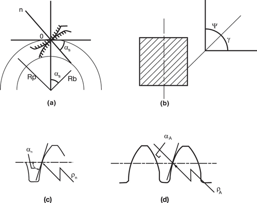
For general industrial purposes, helicoid sections for worm and wheel are mostly involute helicoids and screw helicoids. Both of these helicoids can be generated with a straight line generatrix, therefore their tooth geometry is simpler. Involute helicoids may be generated either by hobbing or by lathe (see Figure 2). When it is generated by lathe, half of the cutter included angle must be equal to the lead angle of base helix. From the properties of the involute helicoids, it is known that the teeth flank will have some curvature in its transverse section and the radius of curvature at pitch point will be given by:
ρ = Rp Sin αs (1)
A normal section of the curvature will have a radius of curvature:
ρn = Rp ( Sin ψn Cos2ψ ) = Rp ( Sin αn / Cos2 ( 90 –γ ) ) = Rp ( Sin αn Sin2 γ ) (2)
The radius of curvature at axial section is related with the radius of curvature at normal section according to the following equation:
1/ ρA = (1/Cos γ )* ( Cos αa / Cos αn )3 [( 1 / ρn ) + ( Sin2 γ / Rp ) * Sin αn * ( 1+ Cos2 αn )] (3)
By putting the value of ρn from equation (2) in the equation (3) and simplifying it, the following equation is obtained:
1/ ρA = ( Sin2 γ / Rp ) * [( 1 / Sin2αn ) + Sin αn * ( 1+ Cos2 αn )]
* (1 / Cos γ )* ( Cos αa / Cos αn )3 (4)
The radius of curvature at the axial section of the involute worm is obtained. The radius of curvature at axial section of screw helicoids is independent of its axial pressure angles, lead angle, and pitch diameter of the worm or wheel. Here curvature is a constant and is equal to zero.
Curvature Radius at a Section Parallel to Axial Section
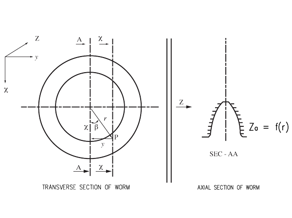
The radius of curvature of the worm tooth flank at a point P is to be determined [2]. We follow Cartesian coordinate system, in which the central point of the transverse section of the worm is the origin (see Figure 3).
The worm axis represents Z axis, and the X & Y axis are as shown in the transverse section of worm. The coordinate of any point P on the helicoids (flank) will be the function of x, y & z. But for any section parallel to axial section, the value of y will be constant. Therefore, for a particular point P, z is the function of x only. From the definition of the pressure angle at any section it is known that:
Tan α = ∂Z /∂X
Or ( 1 / Cos2 α ) = 1+ (∂Z / ∂X )2
The point P in xx section may be indicated either by Cartesian coordinate system x, y, and z or by the polar coordinate β, r, z, so it is given that:
r2 = x2 + y2 and Tan β = y/x
In the worm axial section AA, Ya = 0, Xa = r and za being a function of r is given by za = f ( r )
Therefore, Tan αa = ( ∂ f ( r) / ∂ r ) ; 1/ ρa = – Cos3 αa = ( ∂2 f ( r) / ∂ r2 )
The equation to the helicoids plane is:
z = f ( r ) – ( β L / 2π )
Therefore, in section xx, Tan α = ( ∂ z / ∂ x )
= ( ∂ f ( r) / ∂ r ) (∂ r / ∂ x) – ( ∂ β / ∂ x ) ( L / 2 π )
= ( ∂ f ( r) / ∂ r ) ( x / r ) – ( L / 2 π ) ( y / (x2 + y2))
= Tan αa Cos β + Tan γ Sin β (5)
1/ ρ1 = – [Cos3α ( ∂ z / ∂ x )]
= – Cos3α [(∂2 f ( r) / ∂ r2)(∂ r / ∂ x)2)+( ∂ f ( r) / ∂ r )(∂2 r / ∂ x2) – ( ∂2 β / ∂ x2) (L /2 π )]
= + Cos3α [ (Cos3 β / ( ρa Cos3 αa )) – (Tan αa Sin2 β / r) + (2Tan γ Sin β Cos β / r) (6)
Relative Curvature of the Worm and Wheel Teeth Profile
1 / ρ = ( ro2 Sin α – (a2 / ρ1) + a ) / ( 1-(a / ρ1))2 (7)
When, a = ( ( Rp – r Cos β ) / Cos α ) (8)
It is to be noted that for the present coordinate system ρ2 is positive when wheel flank is convex. ρ1 is positive when worm flank is concave [2].
Example 1
To calculate the relative curvature of an involute helicoid worm at a section which is parallel to axial section, the point of contact is assumed to make an angle approximately 20 degree with vertical plane. The worm have following gear parameters:
(Axial) Module ma=5, No. of start of worm Z1 = 1 diametrical quotient q = 10. Root diameter droot = 38.20 mm. Pitch circle diameter do = 50mm. Addendum diameter da = 60 mm, lead angle (at pitch circle diameter ) γo = 5.71059o. Normal pressure angle ( at pitch circle diameter ) n = 20o. Working center distance a’ = 125mm. Wheel teeth number Z2 = 40. Transmission ratio i = 40.
Solution: The exact coordinate point of contact in this case will be β = 20.762, r = 26.28 mm. (see ref. 3 ). The geometrical relations for involute helicoids worm gear is given as:
Tan2 γg = Tan2 αt = Tan2αao + Tan2 γo….(i)
Tan αao = Tan αno / Cos γo……………..(ii)
From equation (ii) αao = 20.09179 degree. Here, Rp = 25 mm
From equation (i) αt = 20.767152 degree
Substituting the values in equation (4) ρa = 273.80396 mm
From equation (5)
Tan α = Tan 20.09179 Cos 20.762 ÷ Tan 5.71059 Sin 20.762
= 0.3774808
α = 20.6806o
From equation (6) ρ1 = 278.91121 mm
From equation (8) a = 0.4559783 mm
From equation (7) ρ = 35.88828 mm
Example 2
To calculate the relative curvature of a screw helicoids worm at a section which is parallel to axial section. The point of contact is assumed to make an angle 20 degree with vertical plane. The worm of wheel have the same gear parameters as in example 1 except instead of normal pressure angle, axial pressure angle
( at p.c.d.) = 20 degree.
Solution: The contact position remains almost same for all types of worm and wheel which has got straight line generatrix (see note * at end). Therefore, here also it may be taken as:
β = 20.26 degree, r = 26.28 mm
At any position in axial section of screw helicoids 1 / ρa = 0
From equation (6) 1/ ρ1= 0.00070569 ,ρ1 = 1417.05 mm
a = 0.4559783 mm
From equation (7) ρ = 35.79487 mm
Example 3
For the gear pair of example 1 calculate the relative curvature at a section parallel to vertical plane making an angle approximately equal to 30 degrees.
Solution: The exact point of contact in this case will be at β = -28.155 degree, r = 28.35. The negative sign attached with indicates angle is at opposite side of assumed direction. So it can be dropped.
From equation (4) 1 / ρa = 0.00365224 ρa=273.80396 mm
From equation (5) α = 20.2888 degree
From equation (6) 1 / ρ1 = 0.00325236 ρ1= 307.46823 mm
a = 0.00484252 mm.
From equation (7) ρ = 34.679834 mm.
Example 4
For the gear pair of example 2 calculate relative curvature at a section parallel to vertical plane, making an angle of 30 degrees.
Solution: β = 28.1o, r ≈ 28.3 mm α = 20.2888 degree
From equation (6) 1/ρ = 0.000068584, ρ = 14580.64 mm
From equation (7) ρ = 34.665665 mm.
Example 5
For the gear pair of example 1 calculate relative curvature exactly at axial section.
Solution : Calculated ρa = 273.80396 mm, β = 0 degree,
r = 25 mm = Rp
α = αa = 20.09179 degree, a = 0
= ro2 Sin 20.09179o
ρ = 100 Sin 20.09179o
= 34.3525 mm
Example 6
For gear pair of example 2, calculate relative curvature exactly at axial section
Solution: Here t = ro2 Sin αa = 100 Sin 20o = 34.220 mm
Conclusions
Results show that the difference in relative curvature is more prominent toward the axial plane. As shifted from the axial plane, the difference in relative curvature between screw helicoids and involute helicoids goes on reducing.
It is noticed that the amount of relative curvature at a particular section is more in involute helicoids than the screw helicoid. In terms of only Hertzian contact stress (ignoring other factors like effect of contact ratio), involue helicoids should have better strength.
References
1) Niemann G. Machinen Elemente-Entwerfn. Berechnen und Gestalten im Maschinenbau-ZweiterBand, Springer Verlag, (1965)
2) Karl Kutzbach and Niemann G. Schnecken triebemit flussiger Reibung VDI-Forsch-Heft 412
3) Buckingham E. Analytical Mechanics of Gears. Dover Publications Inc. (1963)
4) Merrit H.E. Gear Engineering. A.H. Wheeler & Co Pvt. Ltd. (1984)
* “A comparison of figures shown a very close agreement between the forms and positions of the projections of the contact lines of the screw helicoids and the involute helicoids on the end sections of the worms, particularly those portions of them which lie on the thread sections of worms. Therefore, except for critical drives, which should always be analysed in detail, the conditions on either type of helicoids may be used as a very close approximation to those on any other type of helicoids with a straight line generatrix”—Buckingham.


