


Grinding helical gear teeth or other helical forms such as drill flutes by the method of advancing a grinding wheel along a helical path is one of the most accurate methods of producing a given profile. This motion is achieved by rotating the part while advancing the grinding wheel axially. For gear teeth, this method is in competition with older technologies which generate the tooth profile by having the grinding wheel emulate a rack or worm. It is not the intent of this article to critically compare these methods, but it should be noted that full form grinding is not a generating process. This article intends to:
-
- State the equations required to define the grinding wheel form, knowing the helical part form; State the equations required to define the helical part form, knowing the grinding wheel form; Discuss some uses of this geometry for the gear or tool manufacturer.
These equations will be mostly useful for computer applications. During this discussion you may wish to refer to the glossary of terms in Table 1 and the symbol definitions in Table 2. The underlying principle of full form grinding is that, at the point of finishing, the normal through the common point of contact between the grinding wheel surface and the helical part surface must intersect the grinding wheel axis. This principle applies to both external and internal grinding. Obviously, no solution will be found whenever the given form has a region where this principle cannot be applied. We will bypass the tedious derivation of these equations and simply state them as directly as possible.


It is often only necessary to derive the form of a grinding wheel (or milling cutter) from a known helical part form, but at times it may be required to derive the helical part form from a given grinding wheel form. Although these two geometries are based upon the same principle, separate sets of equations are required to find the desired form: one set to describe the wheel form; and one set to describe the helical part form.
Two axis systems will be used to set up the required equations. The helical part will use the X, Y, and Z axes, and the wheel will use the X’, Y’, and Z’ axes. The axis of rotation of the helical part is the X axis, and the axis of rotation of the wheel is the X’ axis. These axes will always lie in parallel horizontal planes separated by the center distance, C. The X’ axis will always be above the X axis, even for internal grinding.
The vertical axis, Y’, is coincident with the vertical axis, Y, but inverted such that at any common point y+y’=C
The Z and Z’ axes will rise vertically from the plane of the paper when the wheel setting angle, b, is zero. When the wheel setting angle is not zero, the X’,Y’, and Z’ axis system will swivel to the wheel setting angle about the Y’ axis.
For simplicity we will always consider the helical part as being defined in the X-Y (axial) plane. The form will be described by an array of closely spaced coordinate points and the slope associated with each point. In practice, of course, the form may start off being defined (by line-arc geometry, for example) in some other cutting plane and cranked along the helix by some utility computer program to the axial plane in point-slope format. It is a fairly simple procedure to pick both points and slopes from forms defined by line-arc geometry. A single tooth or space is conventionally viewed centered on the Y axis with positive Y coordinates.
The grinding wheel form, (xw,yw), will always lie in its axial (X’-Y’) plane. For the following equations, refer to the glossary in Table 1 and the symbols in Table 2.
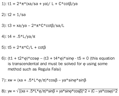
Finding the Grinding Wheel Form from the Known Helical Part Form
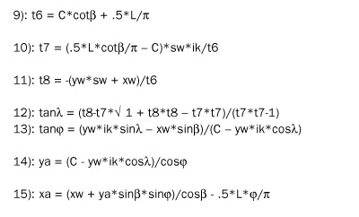
Finding the Helical Part Form from the Known Grinding Wheel Form
Surprisingly, the solution for the helical part form is quite simple and involves no transcendental solutions.
-
- The angle, j, has its vertex at the helical part axis and is the angle from the (X-Y) plane to the common point of finishing. There may be more than one solution for j in equation (6) so if the wheel profile point (xw,yw) seems to be a “wild” point, you will need to search for another solution for j. One technique is to always search for every solution and use the one that yields the most reasonable point, (xw,yw). After all the helical part profile points (xa,ya,sa) have been processed, there will be a corresponding array of grinding wheel profile points (xw,yw) which can be fed into a curve-fitting utility program in order to convert the grinding wheel form to a line/arc format. Finding the Helical Part Form from the Known Grinding Wheel Form
The angle, l, has its vertex at the wheel axis and is the angle from the (X’-Y’) plane to the common point of finishing. After all the wheel profile points (xw,yw,sw) have been processed, there will be a corresponding array of helical part profile points (xa,ya) which can be fed into a plane shifting utility program to place the form in any required cutting plane, and then into a curve-fitting utility program in order to convert the helical part form to a line/arc format.
Applying the Geometry
Borazon plated grinding wheels have been very successfully applied to full form grinding because their geometry is unchanging throughout their life. Form-dressed vitrified wheels require a change in center distance after each dressing, and therefore need to have the form recalculated regularly.
A problem with Borazon plated wheels is that they are expensive when used with small manufacturing lots and usually wind up as excess inventory. These wheels may be reused in two ways: 1) depending upon the gear class, a wheel may be able to cut a gear with a few more teeth or a few less teeth than it was designed for, and; 2) a wheel may be used as a rougher if it can leave a reasonable amount of finishing stock all around. These equations will work in both cases to find the resulting gear form, which can be compared (usually by graphic overlay) with the theoretical form.
A special case may be made for dressable vitrified Borazon grinding wheels. These wheels are expensive, but with a single dressing may cut as many gears as a plated wheel, and there are still many dressings left. These equations will find the form to dress on the wheel for any center distance change through the life of the wheel.
These equations apply not only to gears, but to any helical form. A helical gash hob is usually designed to have a radial face. This requires the grinding wheel form to be calculated as a curved form for accurate sharpening. If the gash face is not sharpened correctly it will cause a profile error in the hobbed part.
Wheel forms for grinding helical flutes in drills and taps can be calculated. Usually, non-symmetrical parts with an undercut on one side of the profile will require the part form to be rotated (or have an equivalent axial shift) to establish a workable wheel form. This rotational adjustment is often accomplished by trial and error, but the computer still makes fast work of it.
Internal acme threads or ball-nut threads can be ground. These equations are especially useful when the thread lead is large so that the maximum possible setting angle is less than the thread angle. The resulting grinding wheel form will be quite different from the thread form.


